
PV Ribbon for Solar Module Interconnection
Choose interconnect, busbar, BC, SMBB, 0BB or low-temperature ribbon for the cell layout and stringing process. Raytron also offers copper-aluminum composite ribbon for designs seeking to reduce copper use. Compare conductor geometry, solder coating and mechanical requirements before requesting samples or a quote.
On this page
Choose by function, section and surface
Scroll horizontally to read all columns. Keep the conditions and units with each value.
| Requirement | What it defines | Product information |
|---|---|---|
| Cell-to-cell connection | Interconnect path and cell pad geometry | Interconnect ribbon |
| String current collection | Busbar section, path length and joints | Busbar ribbon |
| Rear-contact layout | Rear pads, routing and solderable zones | BC ribbon |
| Multiple or zero-busbar layout | Line count, conductor section and equipment handling | SMBB ribbon · 0BB ribbon |
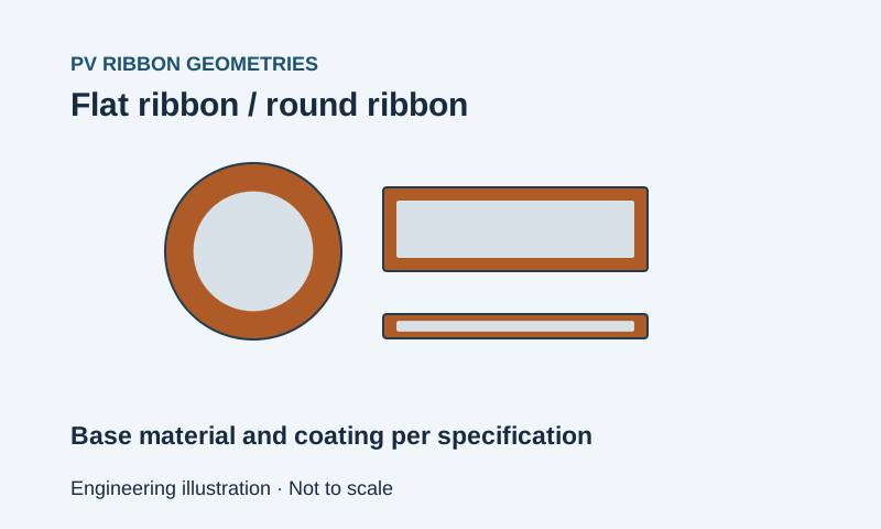
| Round section | Bare/finished diameter, coating and mechanical condition | Round composite solar wire |
| Lower soldering window | Coating alloy and the cell/stringer process | Low-temperature ribbon |
| Copper-aluminum construction | Layers, section and resistance against the copper baseline | Composite PV ribbon |
Specify the ribbon for the module
Provide the cell drawing, current path, round or flat dimensions, coating alloy/thickness, mechanical targets, camber and spool format. Cell technology, conductor shape and solder coating are separate choices.
Define the sample trial
Check dimensions and coating, then run the intended stringer. Compare joint strength and resistance using the stated methods. Define the module-level tests for the project; a ribbon description does not establish a module certificate or a fixed power gain.